Download
Alginate Hydrogel Microspheres(1)

Preparation of alginate hydrogel microspheres with Microdroplet/Microsphere Generator

by acetic acid cross-linking gelation

Experimental Purpose:In this application note, alginate hydrogel microspheres with high monodispersity are prepared with Microdroplet/Microsphere Generator. Drop-Surf Droplet Generation Oil is used as the continuous phase and chelated Ca-EDTA and sodium alginate solution is used as the dispersed phase, and the microdroplets are cross-linked by Ca2+ released in the acid cross-linking reagent solution. Finally, alginate hydrogel microspheres with extremely high monodispersity (CV<5%) are obtained.

FEATURES & BENEFITS

Introduction

Hydrogels are an important class of soft materials with far ranging applications in drug research, drug delivery, tissue engineering, food and pharmaceutical sciences. From a vast library of hydrogel forming (bio)polymers, alginate, as a natural polysaccharide, has attracted great attention in the biomedical field because of its low toxicity, mild ionic cross-linking conditions, good biocompatibility and biodegradability[1]. Currently, it is reported that micrometer-sized alginate particles act as bioscaffolds for 3D cell culture units to simulate the matrix environment of cell growth, which are widely used for the encapsulation, culture and monitoring of living cells in pharmaceutical research and tissue engineering [2]. Uyen N.T.T et al. found that alginate microgels particles can not only control the release rate of drugs, but also deliver drugs to specific therapeutic targets, and alginate can be directly degraded and excreted from the body through metabolism after drug release [3]. Typically, alginate microgels particles are prepared by ionic cross-linking of alginate solution with divalent cations such as Ca2+, Ba2+, Cu2+, Cd2+ and Sr2+ after the formation of droplets. For example, an aqueous sodium alginate is dropped into excess calcium chloride aqueous solution, and alginate microgels are prepared by stirring or ultrasound [4]. However, the microgels produced by this method have some shortcomings such as poor monodispersity of particle size and irregular shapes.

Alginate microgels particles with precise control over size, shape and morphology can be produced by droplet-based microfluidics[5]. Generally, an aqueous sodium alginate solution is emulsified and dispersed in oil phase in microfluidic device, and cross-linked gelation with Ca2+. This fast reaction of cross-linking occurs immediately and typically results in clogging and nonuniform drop formation. To overcome these problems, the generation of droplets and cross-linking gelation should be separated. Zhang et al. reported that CaCO3 nanoparticles are dispersed in the alginate solution, and can be dissolved under acidic conditions after drop formation[6]. However, the dissolution of solid CaCO3 particles causes a heterogeneous distribution of Ca2+ inside the droplets and diminishes the homogeneity of the resulting particles. In addition, the agglomeration of nanoparticles will also lead to the blockage of the small microfluidic channels.

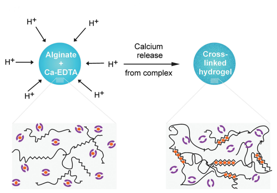
To address the above problems, FluidicLab provides an effective strategy to control the release of Ca2+ into alginate aqueous solution to form hydrogel particles based on current works of Utech et al. [7] The schematic diagram is shown in the follow picture. The dispersed phase (containing Ca-EDTA chelate and sodium alginate) and the continuous phase (Drop-Surf Droplet Generation Oil) are pushed into a microfluidic chip by FluidicLab Microdroplet Generator, and droplets are generated and collected in a container filled with the cross-linking reagent (acetic acid). Once contacted with acid, the binding of H+ and EDTA releases Ca2+, which cross-links with alginate to gelation and obtain solidified alginate hydrogel microspheres.

alginate hydrogel microspheres
ReagentsMicrodroplets Generation Oil (Drop-Surf, 2% surfactant by weight, FluidicLab)
Demulsifier (Drop-Surf)
Sodium alginate (FluidicLab)
Glacial acetic acid (Macklin, A801295-500 mL)
Anhydrous calcium chloride (General-Reagent, P1902809)
0.5 M EDTA (Macklin, E885215-1L)
Sodium hydroxide (Macklin, S817971-500 G)
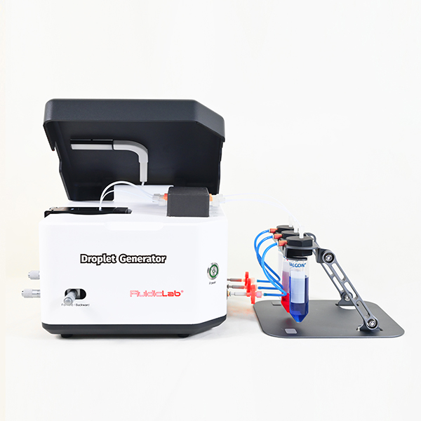
EquipmentMicrodroplet/Microsphere Generator (Fluidiclab, 2 pressure channels)
An air compressor with an air treatment device
An optical microscope for particle size measurement
A personal computer (PC, WINDOWS 7, or 10, or 11)
Centrifuge tubes (Falcon, 15 mL REF 352097)
Centrifuge tubes (1.5 mL)
A PDMS standard chip holder
PDMS-FF-100 μm chips (FluidicLab)
A pH Meter (Mettler TOLEDO, Standard Edition)
Polyurethane tubing (PU, 4 mm outer diameter, 6 mm outer diameter)
Poly (enther-ether-ketone) tubing (PEEK, 1.6 mm out diameter) and connectors (1/4-28 UNF)
A high-speed centrifuge (Hunan Xiangyi, H1850)
Syringe tip filters (25 mm diameter, 0.22 μm, PTFE membrane)
Syringes (10 mL)

1.Reagents preparation:

(1) 2 M CaCl2 solution:
2.2197 g of CaCl2 (MCaCl2=110.984 g/mol) is dissolved into pure water. Fix the volume to 10 mL.
(2) 2% (wt%) sodium alginate solution:
0.2 g of sodium alginate powder and 9.8 g of pure water are mixed homogeneously and heated to 60℃ to be dissolved completely.
(3) 2 M NaOH solution:
1.6 g of NaOH (MNaOH= 39.997 g/moL) is dissolved into pure water. Fix the volume to 20 mL.
(4) 240 mM Ca-EDTA solution (pH=7.2):
1.2 mL of 2M CaCl2, 4.8 mL of 0.5 M EDTA and 5 mL of pure water are mixed homogeneously. Add 2M NaOH into the solution to adjust pH to 7.2, finally fix the volume to 10 mL.
[Note] The volume of NaOH added in the following table is for reference only. You should determine the volume of NaOH solution based on your own measurements.

No.2 M NaOH volume (μL)pH
103.78
210004.73
31005.11
4405.45
5155.82
636.02
736.29
826.65
917.14
Total volume1164/

(5) Preparation of the dispersed phase (1% sodium alginate, 120 mM Ca-EDTA):
A mixture of an equal volume of 240 mM Ca-EDTA solution and 2% sodium alginate solution is vortexed homogeneously to obtain the dispersed phase. Filter the solution with a 0.22 μm syringe filter.
(6) Preparation of 1% acetic acid solution in oil:
5 μL of glacial acetic acid and 495 μL of Droplet Generation Oil are mixed homogeneously with vortex to obtain a 1% acetic acid solution.

2.Preparation of microdroplets:

(1) Microfluidic devices set-up
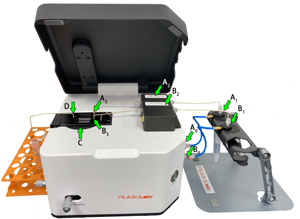
For a more detailed installation and connection of Microdroplet/Microsphere Generator, refer to the User Guide V.1.0 Of Microdroplet/Microsphere Generator, section 2. Installation and connection of Microdroplet/Microsphere Generator. The connection is as follows (steps ③-⑦ are shown in the figure below):
① Connect the devices with PU tubing in the following order:
The air compressor — the air source processing device — the Microdroplet/Microsphere Generator
② Connect the device to the power supply and PC, respectively.
③ Connect A0 (the pressure channel 1 outlet) and A1 (the continuous phase reservoir), B0 (the pressure channel 2 outlet) and B1 (the dispersed phase reservoir) with PU tubing, respectively;
④ Connect A1 (the continuous phase reservoir) and A2 (the flow sensor channel 1), B1 (the dispersed phase reservoir) and B2 (the flow sensor channel 2) with PEEK tubing and 1/4-28 UNF, respectively;
⑤ Connect A2 (the flow sensor channel 1) and A3 (the continuous phase inlet of the PDMS chip), B2 (the flow sensor channel 2) and B3 (the dispersed phase inlet of the PDMS chip) with PEEK tubing and 1/4-28 UNF, respectively;
⑥ C is a combination of a PDMS standard chip and a chip holder, which is sealed by 6 silicone connector seals;
⑦ The PEEK tubing is inserted into the chip & chip holder outlet (D) for emulsion output.

Microdroplet/Microsphere Generator

(2) Installing FluidicLabSuite software and adding equipment:
Refer to the section 3.1 Installation of FluidicLabSuite Software in the User Guide V.1.0 Of Microdroplet/Microsphere Generator.
(3) Preparation of alginate microdroplets:
① 5 mL of Droplet Generation Oil and 1 mL aqueous solution into the corresponding reservoirs respectively:
Reservoir 1 (controlled by Pressure Channel 1): Droplet Generation Oil;
Reservoir 2 (controlled by Pressure Channel 2): the dispersed phase.
② For the use of the integrated camera and flow sensors, refer to the section 3.2 Equipment Addition of FluidicLabSuite Software in the User Guide V.1.0 Of Microdroplet/Microsphere Generator.
③ Turn on the air compressor and air source treatment device.
④ A centrifuge tube is placed at the emulsion outlet to collect the pre-waste liquid .
⑤ Set channel 1 pressure and channel 2 pressure by FluidicLabSuite control to exhaust the air in the PEEK tubing and the microchannels of chip;
Tips: Due to its high viscosity, we kindly suggest you set a higher pressure in the dispersed phases than in the continuous phase. For example,
Pressure Channel 1 (controlling the oil phase): 150 mbar;
Pressure Channel 2 (controlling the aqueous phase): 900 mbar.
⑥ After the PEEK tubing and the microchannels of chip are filled with liquid, switch the control mode from pressure control to flow rate control. The flow rates of channels 1 and 2 are set as 15 and 8 μL/min, respectively.
⑦ The smooth output of target flow rate can be quickly achieved through adjusting the feedback value.
⑧ After a few minutes, collect a drop of the emulsion onto a hydrophobic substrate base, and ensure the uniformity of droplet size with an optical microscope.
⑨ After that, collect the emulsion into a 1.5 mL centrifuge tube containing cross-linking reagent solution.
⑩ Collect the emulsion for 20 minutes, and 20 minutes of cross-linking time with gently vibration is allowed for cross-linking gelation.

3. Aftertreatments:

① Remove the oil phase (at the bottom of the tube) with a pipette.
② Add 2x volume of Drop-Surf Demulsifier to the microspheres. For every 100 μL microspheres, add 200 μL Drop-Surf Demulsifier.
③ Vortex the mixture for 20 seconds, then centrifuge it at 1000 rpm for 30 seconds. Remove the demulsifier at the bottom of the container.
④ Repeat steps ② and ③ 1~2 times, until all white microspheres on the top of the container change into transparent.
⑤ Add 3x volume of PBS buffer to the microspheres. For every 100 μL microspheres, add 300 μL PBS buffer.
⑥ Vortex the mixture for 20 seconds, then centrifuge 1000 rpm for 120 seconds. Remove PBS buffer at the upper of the container.
⑦ Repeat steps ⑤ and ⑥ 1~2 times.
⑧ Finally, the solidified alginate hydrogel microspheres are obtained and dispersed in PBS buffer.

4.Cleaning of Microdroplets/Microsphere of Generator:

The PEEK tubing, the flow sensors and the microchannels of the chip should be cleaned after the experiment. Otherwise, the reagents remaining in the flow channels could possibly damage the flow sensors and clog the microchannels of the chip. For details, please refer to the Instruction Card of Microdroplet/Microsphere Generator.

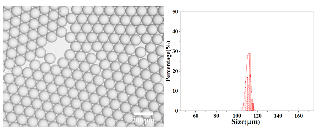
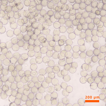
The alginate microdroplets have an average particle size of 111.04 μm, and have extremely high monodispersity (coefficient of variation: CV=2.01%). The picture and particle size distribution are shown as follow:

Alginate Hydrogel Microspheres

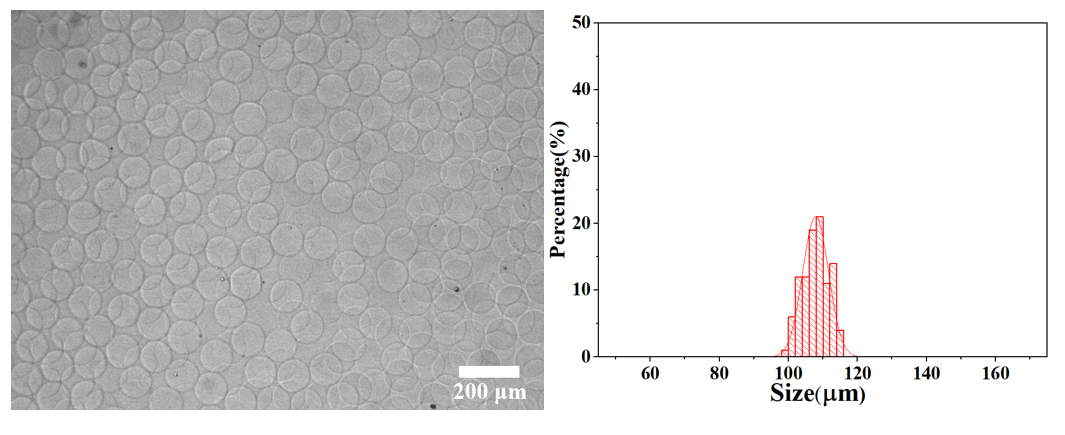
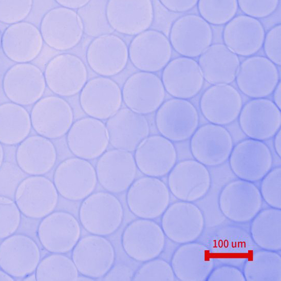
After cross-linking gelation, the average particle size of alginate hydrogel microspheres is 107.86 μm, and have extremely high monodispersity (CV=3.47%). The picture and particle size distribution are shown as follow:

Alginate Hydrogel Microspheres

Key points of the experiment

1.The cross-linking reagent solution (1% acetic acid in oil phase) is acidic (pH<5).
2.In this application note, the dispersed phase should not contain free Ca2+. For example, a medium containing free Ca2+ is not applicable for use in the dispersed phase.
3.The viscosity of the dispersed phase is higher than that of the continuous phase, thus, the pressure of the dispersed phase is higher than that of the continuous in the same flow rate. Due to its high viscosity, we kindly suggest you set a higher pressure in the dispersed phase than in the continuous phase.
4.Due to its low concentration, the final obtained microspheres may not be observed when dispersed in PBS buffer. You can add a small amount of free Ca2+ into the PBS buffer, or disperse the microspheres in water.

References

[1] Ching S. H., et al. Alginate gel particles–a review of production techniques and physical properties, Crit. Rev. Food Sci., 57, 1133-1152 (2015).

[2] Wang H , et al. The use of micro- and nanospheres as functional components for bone tissue regeneration , Tissue Eng. Part B Rev., 18, 24-39 (2012).

[3] Wan. J, Microfluidic-Based Synthesis of hydrogel particles for cell microencapsulation and cell-based drug delivery, Polymers, 4, 1084-1108 (2012).

[4] Rowley J.A., et al. Alginate hydrogels as synthetic extracellular matrix materials., Biomaterials, 20 , 45-53 (1999).

[5] Bhatia, S. N., et al. Effect of cell–cell interactions in preservation of cellular phenotype: cocultivation of hepatocytes and nonparenchymal cells. FASEB J. 13, 1883–1900 (1999).

[6] Zhang H., et al. Exploring microfluidic routes to microgels of biological polymers, Macromol. Rapid Comm.28, 527-538 (2007).

[7] Utech S., et al. Microfluidic generation of monodisperse, structurally homogeneous alginate microgels for cell encapsulation and 3D cell culture,Adv. Heal. Mater., 4, 1628-1633 (2015).


NEED HELP OR TECHNICAL INFORMATION?

NEED HELP OR ADVICE?

For any help to determine what microfluidic instruments you need, you can contact us! Our experts will help you build the best microfluidic setup for your application, with our state-of-the-art microfluidic line.

GET IN TOUCH

Talk to our experts
Contact Form

PRODUCTS

Fluid Control Systems
Droplet Microfluidic Systems
LNP Synthesis System
Measurement & Detection
Microfluidic Chips
Microfluidic Reagents

APPLICATION

Hydrogel Microspheres
Nanoparticles Packs
Dissolvable gel beads

INDUSTRY

OEM Products

CONTACT

  • 315, Building 1, No. 8 Memorial Road, Yangpu District, Shanghai, China
  • +86 021-65103566